


Control Point Survey : Outline
OutlineControl Point SurveyIn the unique ice-covered environment that is Antarctica, control point surveys required taking independent astronomical surveys at each ice-free area to obtain latitudinal and longitudinal bearings. However, unconformities in the surveys between areas or in large scale maps were points of concern.
Therefore, we started integrating our geodetic networks in the 1960's. In the 1970's, we incorporated the use of electro-optical distance measurements(Geodimeter Model 8) that allowed accurate measurements over long distances and high-precision theodolites (Wild T3). However, our integration work was restricted to the southern vicinity of the Syowa station as the distances between ice-free areas in other parts were too great for line of sight confirmation. At the start of the 1990's, the advent of GNSS(GPS) facilitated continuous GNSS(GPS) observation and SCAR campaign surveys, accurately integrating the coordinates of the Syowa station into the global geodetic network Currently, IGS station at Syowa station (SYOG) is being used as a control point survey origin for GNSS relative positioning, helping the effort to build a global geodetic network. 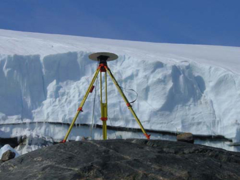
Survey StandardThe first survey standard used in the Antarctic region was GRS-67 which was in use for a long time for control point surveys and topographic mapping. GRS-67 is Earth ellipsoid which was adopted as the international geodetic reference system at the 14th meeting of the IUGG (International Union of Geodesy and Geophysics) held in 1967, and widely used until it was superceded by GRS-80 adopted at the 17th meeting of the IUGG held in 1980.
After the 25th meeting of SCAR in 1998, we changed to using the ITRF (International Terrestrial Reference Frame) as the geodetic reference system, based on the recommendation issued by the Working Group on Geodesy and Geographical Information. In March 2001, the coordinates of IGS station (SYOG) for GNSS (GPS) continuous observation and VLBI observation station at Syowa station were incorporated into ITRF2000 realization, and registered with the IERS (International Earth Rotation and Reference System Service). Coordinates of control points observed after the 33rd JARE (1991) has been recalculated based on ITRF2000 using IGS station at Syowa station (SYOG) as the fixed station, and using the GRS80 ellipsoid. All coordinates of control points (including renewal and recalculation) provided by this service has been updated based on ITRF2000. Geodetic Coordinate System
|